|
|||
|
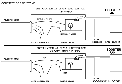
Here are the Greystone installation instuctions: 1. Disconnect and lock-out all power sources during installation as severe injury or death can result from electrical shock due to contact with high voltage conductors. Ensure all installations are in compliance with applicable electrical codes and that the installation is completed by qualified installers familiar with the standards and proper safety procedures for high-voltage installation. Never rely on status indicating devices only to determine if power is present in a conductor. 2. Mount sensor in a convenient location, with-in or adjacent to the breaker panel. Alternatively the sensor can be installed inside the dryer electrical compartment. 3a. (3-Phase systems) Disconnect and loop the neutral power wire, white, through the current sensor and reconnect. 3b. (220 Vac 3-wire single-phase systems) Determine which of the Hot wires is active for the dryer only. (this is necessary for stacked washer/dryer units). Verify that there is sufficient current to trip the current switch (minimum of 1 amp). If required the wire can be looped through twice to increase the current read by the switch. Loop the HOT power wire trough the current sensor and reconnect. 3c. (120 Vac systems) Verify that there is sufficient current to trip the current switch (minimum of 1 amp). If required the wire can be looped through twice to increase the current read by the switch. Loop the HOT power wire trough the current sensor and reconnect. 4. Connect the fan power supply, as shown 120 Vac max, to the top terminals of the current sensor. 5. Note that the CS-425-HC-0 has a switch rating of 2.5 Amps maximum at 120 Volts. Parts: CS-425-HC-0 Current Switch As always, if you would like to ask more questions about this or other technical topics give us a call at 877-711-4822 - 9-5 PST. Live people for technical and sales support - an Internet first! Disclaimer: Advice and information given through our representatives is checked for usability and conformance with most codes. You as the user, however, have the responsibility for verifying conformance with local codes and standards and ensuring a safe installation. Although HVACQuick.com may employ and use professionals, their advice is not meant as substitute for professional engineering services. It is the customer's responsibility to hire and retain suitable engineering and architectural professionals as required. |
HVACQuick.com
high performance ventilation & green products - large in-stock inventory!
- team@hvacquick.com
- 888-855-7229


